I figured that I would be only updating this on the weekends, there just isn’t enough time during the week to sit down and put in a meaningful amount of work. There is definitely something to say about a solid block of dedicated working time juxtaposed to many sporadic working sessions. It takes a lot of effort to record progress and to then get back up to speed with the progress during a short work session. Anyway, something that has been on my mind recently.
On the chopping block, is the extruder mount for the 3D printer. The first task was to do a mock-up of the belt paths on the actual printer. With the CoreXY arrangement, there are four belt mounts that need to be incorporated into the extruder mount. Based on the paths, the two ‘front’ mounts will contact the belt on the flat side while the two ‘back’ mounts will contact the belt on the toothed side. I modelled some mating teeth into the ‘back’ side of the mount, as seen below.
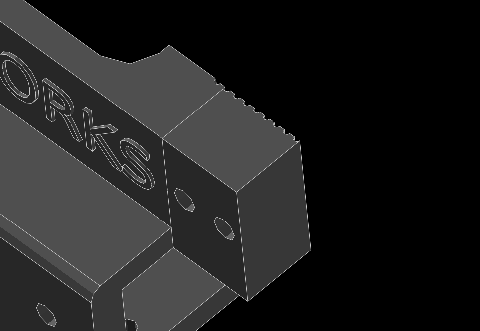
I’m using ‘front’ as the ‘-y’ direction and ‘back’ as the ‘+y’ direction. The clips that hold the belts will need the opposite mating teeth modelled into them, that is, the front clip needs teeth, while the back clip can be smooth. I haven’t started modelling these yet, but they will be relatively small.
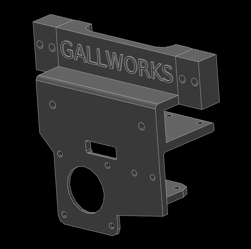
Above is a view of the unit as it stands now. Something that I want to put some thought into before printing a test is where the limit switches will contact. There is not an abundance of mounting points on the printer for limit switches so it will be pretty important to get the extruder mount compatible with the existing mounts.
One other feature I put in for future expansion, is two 4mm bolt holes seen in the middle left of the above image. I’m hoping to use this point to mount the part cooling fan. This is also something I would like to have a preliminary model of before printing the extruder mount itself, just to make sure I haven’t painted myself into a corner while defining that interface. Anyway, that’s all for now!